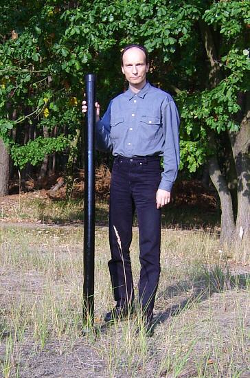
 Technical data
Length: pushed in 1.7 m, apart pulled 18 m
Diameter: down 73 mm, above 4 mm
Wall thickness: down 2 mm, above 1 mm
Segments: 12
Mass: 6.5 kg, approximately 6.8 kg with hose clips
Source of supply: Spiderbeam
Assembly of the hose clips
The hose clips are available as option and the use is recommendable.
They consist of V2A steel, possess inside a sticking rubber film and prevent safely to collapse of individual segments.
According to Con, DF4SA, it is also possible to secure the segments temporary with tape - I did not try out this so far.
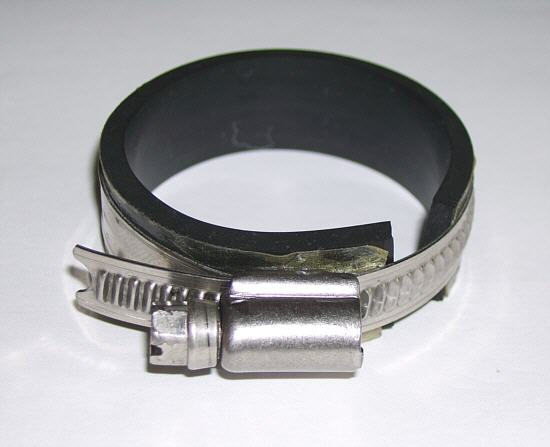 Before one cuts a piece off rubber film of the provided role, the correct length is to determined.
Put the rubber with the paper protective layer around the thicker (lower) end of the segment and cuts it off exactly on the point, who it reached once around the segment.
Take care if you strip away the paper layer.
Otherwise it remains sticking at the paper and not at the rubber.
The rubber film is to stuck on the inside of the hose clip in such a way that an end is completely under the screw.
Thus damages of the mast are avoided when late tightening the hose clip.
Press the now still free end of the rubber film slightly along the metal band.
The top margin of each segment is not covered by a hose clip, nevertheless exists no danger of fraying.
And the attempt to compress the lower segment together to clamp narrower segments fails, because of the wall thickness.
The hose clips as stoppers are sufficient, how also the manufacturer confirmed.
Horizontal building
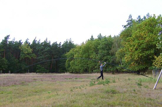 The mast can be very simple build constructed, if it lies on the ground.
Thus the assembly of the hose clips causes no difficulties and one can very easily apart draw the segments.
If someone has doubts to set up such a long mast afterwards alone, then I can calm it down.
Although I am rather skinny as muscular, it succeeded to me without problems.
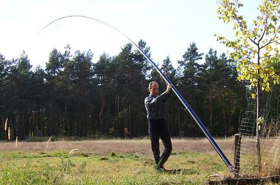 Like Con, DF4SA, already show on his webpage, it goes marvelously, if one treat the mast a thrust bearing.
This can be a larger stone, a tree stump or something like that.
As next go under the completely installed mast from the tip along to the toe and press the mast upward.
Musclemen can pull it up also standing on the toe - which I do not have tried out.
Vertical building
There is still another bulding variant, which might interest all people without enough place.
Fasten the mast on the place, on which it will be errect later.
Than push each segment individually upward.
Pushing upward is relatively simply.
The mast does not weigh any longer than 6 kg, also when pushing out the next to last segment - and even I get lifted, particularly since the point is only 1.7 m over the ground.
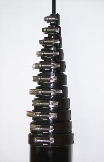 You can master the vertical building only if all hose clips are sitting on the upper ends of the segments, are easily tightened.
Thereby the segments are protected and do not slide back in the mast.
It's looks like a small pyramid.
When I build up the mast I had only to loosen the appropriate hose clip and could push upward the segment.
The loose hose clip slide down automatically.
If the segment does not continue, one needs to tighten the loose hose clip only.
The segments do not have to be drawn tautly apart, since they are held by the hose clips, which resting upon the next thicker segment.
Impossible building
With my tests I tried also to pull apart the segments while the mast stands diagonally.
It don't go!
At the latest with half of the segments the friction is too large by the already freely hanging segments that nothing slide in or out.
Mounting plate
For the attachment of the mast two variants offer themselves: with as broad as possible padded hose clips or with cords.
Who selects the first possibility should use at least as upper clamping point the upper end of the lowest segment - higher places are still better.
The hose clips should not be to small in the diameter, in order to be avoided damages at the mast, and not be too largely, so that the mast leaves itself to in bottom plates as firmly as possible.
The mounting plate must be absolutely stable enough.
The force, which exercises the fattening forced away by the wind, is considerable.
No miracle, because the emphasis lie over the fourth segment, thus at a height of 6 to 7 m.
Multiplied by its mass of 6.5 kg there is a not to be despised torsional moment.
I will not use hose clips, since I cannot implement the upper attachment highly enough.
With me the upper clamping place would be only at a height of 1 m - much too few, in order to enjoy the mast and not to kill passers-by with the broken off mast.
Therefore the 18 m long telescope mast will be used with me only for the portable operation.
In this case it can be secured simply in a few meter height over 3 thick cords and tent pegs in the ground.
Modification of the hose clips
I stressed the hose clips during the building tests.
After a few test series the rubber film separated despite glue layer from the hose clips.
But also after careful handling sand and grass stuck at the adhesive layer out-standing between metal band and rubber film.
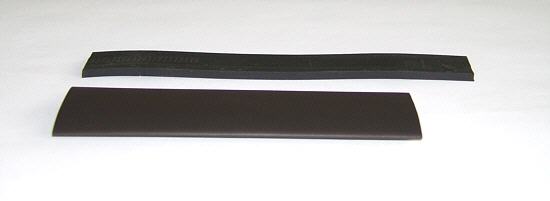 A solution had ago.
And I found it in the form of heat shrink sleeve.
First I used which, which was present still in the junk box.
Unfortunately it was not enough for all hose clips.
Therefore I bought new ones: shrinkage ratio 2:1, diameter before shrinking 19 mm and afterwards 9.5 mm.
Gives it as packing of 10 pices with 20 cm long piece.
For the following modification seven pieces are needed - a few short remainder and 3 intact pieces remain.
The heat shrink sleeve is to cut in each case 23 to 24 mm shorter than the rubber.
Go!
If you want to install the hose clips the first time and want to cover the hose clips with heat shrink sleeve at the same time, stip away the rubber film only on the area, which will not be inside the heat shrink sleeve later.
Leave the adhesive layer unaffected at the leaving part.
This would give additional stop.
I removed the whole and dirty glue film completely.
In any case it makes itself substantially better to bend the metal band of the hose clip halfway straight before the covering of the heat shrink sleeve.
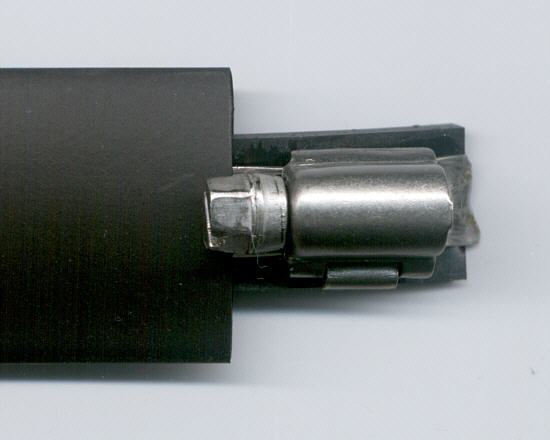
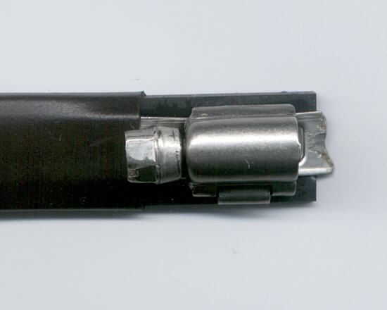 Remember to put the rubber film completely under the screw chassis and release 7 to 8 mm between screw chassis and at the beginning of the heat shrink sleeve.
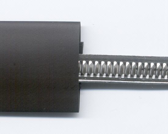
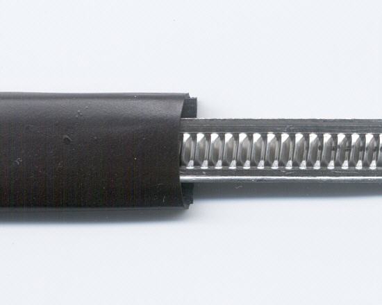 Put the now still free end of the rubber film along the metal band.
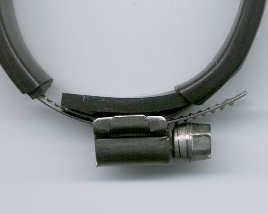 If the sleeve was pulled over the rubber an shrinked, if the hose clip is bent into its form was bent and if the free end was screwed in, it should look like in the photo.
One sees that the free end of the metal band is not obstructed by the shrink sleeve.
But the distance to the screw chassis serves.