Karl H. Hille, DL1VU, described in the magazine Funk 8/1999, pp. 44-47, under the title "The 13 m dipole - an uncompromising, broadband directional antenna" multi-band antenna designed by him.
With a length of 13 m (2 × 6.5 m), this antenna is shorter or longer than a half-wavelength on all bands from 80 to 10 m.
Außerdem verzichtete er ganz bewust darauf, die Antenne in Resonanz zu betreiben.
According to his statement, "the radiation of an antenna is not affected at all by the resonance".
The food point impedances are quite different on the bands.
That's why DL1VU has recommended an open two-wire line or the more practical 450-Ω-line (Wireman).
As a closing height, he has recommended 10 m.
However, he did not reveal the length of the feeding line.
Hille used hard-drawn copper wire with a diameter of 1.6 mm for the antenna wires and the open two-wire cable (chicken ladder).
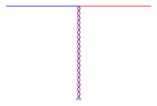 Peter Zenker, DL2FI, made a light and fast-built variant of the 13 m dipole known especially at QRP meetings after 2009: the "Twisted-Hille".
The type of feeding via two insulated, twisted lines line he recommends, is not new.
Dave Gauding, NF0R, and Doug Hendricks, KI6DS, already published this doublet antenna, but they used ribbon cables or computer flat-band cables.
Jim Duffey, KK6MC/5, and Dennis Foster, KK5PY, also contributed to the design, Doug said.
I couldn't find anything on the Internet about the "St. Louis Doublet" presented by Dave Gauding, NF0R, in the QRPp, Spring 1999, pp. 16-19.
However, Doug's description in the QRP-Report, 4/2010, p. 30-31, presented the "NorCal Doublet Antenna" made from one piece of wire, which can still be read at the webpage of the NorCal QRP Club here and here.
Dimensions and modifications
Each half of the antenna wire with a mechanical length of 6.5 m, an electrical length of 6.63 m at velocity factor VF = 0.98, has no resonance on any band between 80 and 10 m.
But 6.63 m is just 0.08 λ, quite short for 3.53 MHz.
So I was looking for a larger antenna and chose a 40 % longer version.
Here is the solution with 2 × 9.5 m for the antenna wire and 8 m for the two-wire cable.
I assumed a velocity factor of VF = 0.98 for the antenna wire and VF = 0.80 for the feeding line.
In the following Javascript, according to the frequency, the wavelength of the antenna wire (S) as well as the wavelength of the antenna wire together with the two-wire line (S+Z) are determined according to the predetermined mechanical lengths and the velocity factors.
The determined lengths in wavelengths should not form an integer multiple of a single number of λ at any frequency, because then the antenna would be highly impedanced to match to us badly.
Materials and construction
I built the antenna in the form of an inverted-v.
This requires only a high clamping point.
With the 5.5 m mast height used, as well as with 9.5 m long antenna wires and 2.8 m long guys, there is an angle of 127° at the top - close to the ideal angle of 120° for an inverted-v.

 For antenna wire and feeding limne I use insulated copper strands with 1.2 mm outer diameter and 0.14 mm² cross-section.
This strand is available with different coloured insulation.
I chose yellow strand because then the wires can be seen well when it is lying on the ground.
After the slight twisting of all 50 cm, I secured the single wires of the feeding line with short pieces of shrink tube.
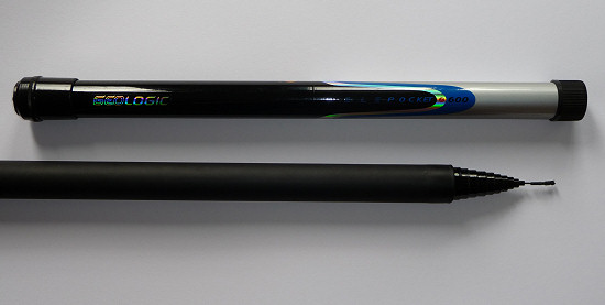 The used telescopic mast by Lambdahalbe is almost 6 m long.
The segments have only a small wall thickness, which means that the mast weighs only 650 g.
The lower segment is well protected against damage by a sledging hose.
In total, the mast has 12 segments and can be stored in a backpack with a transport length of 57 cm.
 The upper segment is too thin to withstand the lateral pull of the two antenna wires for a long time.
I therefore attached the antenna to the transition from the 11. to the 12. segment at a height of 5.5 m.
Using the flexible plastic sleeve of an old banana plug, the antenna can be easily attached to the heel to the next segment.
The transverse hole in the sleeve is used to bind the antenna.
 I often didn't use guys for the mast itself.
Instead, the thin cords (mason's lacing cord) on the two antenna wires and on the feeding line serve as a tilt protection.
These three points form a triangle, which makes the mast sufficiently tilt-proof.
It only becomes difficult when there is strong winds.
If there is a pile or thin tree where I want to build the antenna, I would of course like to use it.
A luggage rubber around the lower segment and the pile is sufficient for fastening.
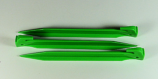
To fix the tensions in the ground, I use bright green plastic herrings, each weighing 22 g.
I bought a 6-pack in the garden department of a nearby Hellweg diy store for 5.99 €.
 These herrings are harder to insert in stony soil, but offer better support in softer soil than thinner metal fastening nails.
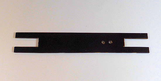
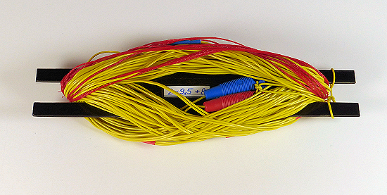
To wind up the antenna, I built a reel made of hard paper.
It measures 4 × 20 cm and is 2 mm thick and stable enough.
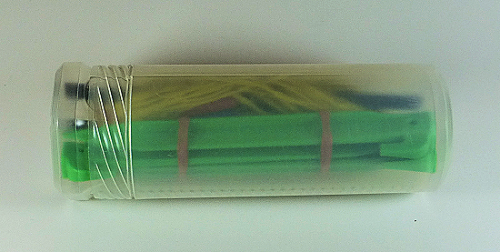
Together with the 3 herrings, the antenna fits into a plastic sleeve of Modulor (item no. 0190485, 6.90 €) with a diameter of 6.5 cm and a minimum length of 20 cm.
Even if the mast is held in the vertical only by the guys on the antenna wires and the feeding lines, its attachment to the lower end is not required.
It is sufficient to sink the mast with the protective cap slightly into the ground.
A small deepening is sufficient for this.