Wire antennas are probably the first choice for portable use on the shortwave amateur radio bands.
I will show you on this webpage how to calculate a Doublet antenna tailored for several bands.
Each doublet antenna consists of 2 radiator halves and a two-wire cable.
Since these antennas are not resonant, they require an antenna tuner and a balun to adapt the asymmetrical transceiver output to the symmetric feedline.
Suitable lengths
Karl H. Hille, DL1VU, came up with the idea of calculate the appropriate location for the connection point of the feedline in the book "Windom- und Stromsummen-Antennen" [1].
In it, he calculates the optimal point on the resonant antenna wire of a Windom antenna.
But the method he used can also be applied to one half of a doublet antenna.
Because there is also a high-impedance at one end and a point with moderate impedance is sought.
However, the algorithm for calculating Windom and current sum antennas has a peculiarity that leads to errors if not observed.
When determining suitable contact points, the currents flowing at a certain point of the antenna of all bands are added.
This creates the characteristic "mountain range" as in the picture below.
In principle, only the summits (maxima) may be considered - side summits are not usable.
The making of the product is more meaningful.
However, for the product, the result is low even if the value on a radio band is low.

The picture above shows the current sum (red) and the current product (blue) on a 9-band antenna for 160 to 10 m to 200 m in length.
The maxima of the sum and the product are roughly in identical places.
But the usable maxima are more recognizable in the product.
The following form outputs the maxima up to a distance of 200 m from the high-impemature end of the wire with with values greater than 0.1.
Up to 9 bands and frequencies can be entered.
The values in brackets indicate the amount of the current product normalized to the maximum value.
Select maximum
A point suitable for all 9 shortwave bands is located at 110.96 m.
![]()
Because then the following wavelengths are present on the antenna wire:
10,37 λ bei 28,030 MHz
9,21 λ for 24,910 MHz
7,78 λ for 21,030 MHz
6,69 λ for 18,090 MHz
5,19 λ for 14,030 MHz
3,74 λ for 10,110 MHz
2,59 λ for 7,015 MHz
1,31 λ for 3,530 MHz
0,67 λ for 1,815 MHz
All that is missing is the feedline.
To do this, you simply drag the feeding point to the transceiver.
The antenna wire then becomes shorter by the length of the depanding feedline.
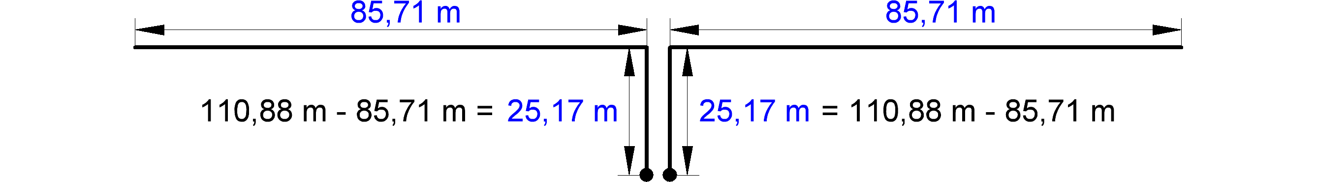
Now calculate the mechanically lengths of the antenna wire lSM and the length of the two-wire feedline lLM from the electrically lengths taking into account the velocity factors of the antenna wire (here VFS = 0.98) and the feedline (here VFL = 0.80).

Below is the calculation based on the selected maximum from the list above and the selected spotlight length.
Control
All that remains is whether the lengths determined in this way also result in the expected low impedances on the selected bands.
The electrically length of the construction connected by the antenna and the feedline shall not be an integer multiples of ½ λ.
In the final step, therefore, the determined lengths are checked and the corresponding wavelengths are output.
The frequencies as well as the lengths of the antenna wire halves and two-wire feedline are from the two previous calculations.
Opportunities and limits
With the calculations shown here, only usable antenna wire lengths and feedline lengths can be determined.
Inferences about the radiation pattern and thus the effectiveness of the antennas are not possible.
In addition, the foot-point impedance will always vary somewhat according to the height of the construction and the existing buildings around.
But these changes should be able to compensate the already necessary antenna tuner.
Literature:
[1] Karl H. Hille, DL1VU: Windom- und Stromsummen-Antennen. Theuberger Verlag, Berlin 2000; Box 73, Order-no. X-9141