Some modifications for the Transceiver K2 published Elecraft themselves on they webpages.
You will find a very voluminous collection of another conversions on the webpage Unofficial Guide to Elecraft K2 Modifications by Sverre Holm, LA3ZA.
The alterations, which I deem as importent for my K2, you will find here.
Maximal output power
I looked for a simple way to reduce the maximal output power of my K2 down to 5 W.
I wound the final transformer with an 1:1 ratio.
This modification is pictured in the manual.
But when I did not pay attention, so I turn the power taper after tuning over the 5 W position to the maximum position (and the "HIGH CUR" message will displayed).
I wanted to become with this modification a maximum power of 5 W (or a little bit more than this) displayed when I turn the power taper at the maximum end.
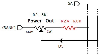 I have insert a new resistor (named R2a with 6.8 kΩ) on one side (labeled cw) of the power taper R2 on the front panel board.
The modification is easy (I thinking it).
Put the front panel board in such a direction so you can read the writing on it.
Separate the right pin of R2 as closely as possible over the board.
It is confined between the potentiometer and the diode.
Use small shears for fingernails for it.
Move the cuted pin parallel to the board.
Remove the remainder of the pin of R2 on the printed circuit board.
Solder one side of the new resistor into the free hole.
The other side connects with the cuted pin of the potentiometer.
Notes that the pin of the potentiometer and the resistor do not touch other sections of the board or the front panel.
A place on the left side of U3 is a good place or it.
That's all!
After these modification as final value 5.2 are displayed.
Something other values for R2a and R2 (by the tolerances) can take something other results for the power.
KBT2 modification
Some K2 users, like me, may want a method to charge the internal battery (KBT2) in the switched-off status without the reverse-polarity protection diode D10 and without the diode/resistor assambly of the KBT2 and without having to install any other jacks.
Here is my solution.
Switch off the internal battery on the rear panel.
Disconnect any power supply or battery connected to the DC power jack.
Remove the bottom cover with the tilt and place the K2 with the front panel on the left side and the bottom side up.
Cut an isulated hookup wires of 11.8 cm = 4.7 inch.
Strip the ends of the wire using 5 mm (0.2 inch) and form small loops on each end.
Solder the wire from the right solder point of D10 (near the 2-D fastener) to one of the free (most left) solder points of S1 (on-off switch).
Note: With "free" I mean the solder points without any connection to other parts of the board.
You can interchange these both points on the switch without problems.
Replace the bottom cover and place the K2 again in the normal position.
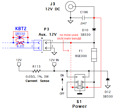 Remove the top cover and the connections to the RF board.
Replace the red wire from the (+) battery terminal to the battery switcher with a new one (without diode and resistor).
Replace all connections to the RF board and the top cover.
Important note: The functions of reverse-polarity diode D10 and the internal self-resetting fuse F1 are the same after the modifications.
But the internal battery is now connected via the fuse directly to the 12V DC jack when the K2 is switched off.
The resistor amounts only 0.05 Ω (thanks to Tom Hammond, N0SS, for this information), so it is undisturbing.
But the fuse protect the switched-off K2 from a short-circuit via the DC jack.
Using an external charger: Switch off the K2.
Plug in the charger (for example a solar panel with controller) in the DC jack.
Switch on the internal battery on the rear panel.
Appendix: Bart, PA3GYU, wrote on 25.8.2004 in my guestbook an advice to my original modification: "I read your Elecraft's K2 - KBT2 modification.
Good thinking!
Still: if you leave out the wire from pin 1 of the AUX.
12V connector to the S1 POWER switch, the self resetting fuse would add extra protection.
Wouldn't this enhance safety?"
I spotted that my modification would safer with it.
So I have eliminated the second wire.
You can see the wire still in the schematic marked as "no more used".
Thanks Bart for the suggestion!
Narrow bandpass filter for 40 m
This modification results in a narrower 40 meter bandpass filter, that reject strong out of band broadcast interference in Europe.
Peter Zenker, DL2FI, set the ball rolling.
He changed the coupling capacitor C6 of 4.7 pF against a 7.02 ceramic filter from Murata.
But Elecraft looked at the specifications on the Murata filter and modified the existing 40 m filter to do almost as well.
And this was preferable to obtaining the ceramic filter and it required only capacitor changes.
![]() C4 and C8 = 1800 pF
C4 and C8 = 1800 pF
C5 and C7 = 120 pF
C6 = 2 pF
L1 and L2 = about 4.4 µH (peaked at 7.050 MHz()
The modeling tool shows for the modified filter the following characteristics: Insertion loss 5 dB; Bandwidths 180 kHz at -3 dB, 700 kHz at -20 dB and 1.5 MHz at -40 dB.
The Murata filter provide an insertion loss of 6 dB and bandwidths of 150 kHz at -3 dB, 400 kHz at -20 dB and 600 kHz at -40 dB.
The Murata filter would be better at 20 and 40 dB.
But this new LC filter has better ultimate rejection - at 5 MHz for example over 60 dB.
The ceramic filter levels out at around 50 dB.
However, both of these filters are much narrower than the original bandpass filter.
Elecraft guess that you might not notice any difference between the booth filters.
I opt for the change of the capacitors.
Optimizing the crystal filter for narrower bandwidths
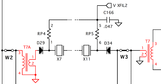 The present matching of the crystal filter (X7 til X11) is a compromise intended to allow the user to vary the bandwidth from narrow (about 300 Hz) to wide (about 1.5 kHz) while preserving respectable loss and ripple characteristics.
If you don't have the KSB2 or like to receive SSB with the CW filter, this modification is NOT recommended.
I've used the values which Roy, AB7CE, suggested:
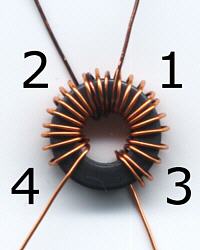
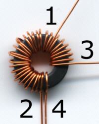
- rewind T7 with 3 turns primary and 22 turns secondary (Photo left),
- wind on the additional T7A 22 turns primary and 10 turns secondary (Photo right).
First make an input matching transformer using 22:10 turns #28 on an FT37-43 core.
This translates to a impedance ratio of about 150:30 Ω.
The nominal IF impedance is 150 Ω and 30 Ω is a good point for optimized coupling to a narrower filter.
Cut the trace from D29 to W2.
Do not remove W2, as inserting the transformer there would interfere with the SSB adapter installation.
The transformer should be mounted on the bottom of the board for a clean installation.
Insert the transformer between D29 and W2.
The side with 22 turns (primary) goes to W2, the other to D29.
One lead of primary and one lead of the secondary goes to ground - use the closest available ground pad.
At the other end of the filter, you'll now have to match the output impedance of 38 Ω to the input impedance of 2 kΩ of MC1350 by changing the winding on T7.
The new winding will have an impedance ratio of √(2000/38) = 7.25, which for a 3-turn primary translates to a secondary of about 22 turns.
After the work use CAL FIL.
The result is overwhelmingly!
Even at the smallest filter setting (here 300 Hz) the amplitude of the signal is nearly at a constant level and higher than before (10 up to 12 dB stronger).
At least for me this modification was very valueable.
4:1 current balun
![]() Charles Greene, W1CG, published in the magazine QRP Homebrewer in April 2002 his article about a 4:1 current balun.
Peter Zenker, DL2FI, tested his version with different cores and turns.
He came out with a balun, which is compared with Charles' original once more impoved.
The manual is published in QRP-Report [1].
Who don't want to built the balun themselves, who could buy the balun as pluggable variant from the QRPproject (QRP-Shop) with the mark "Balun 1:4 QRP".
There is also a manual available.
Charles Greene, W1CG, published in the magazine QRP Homebrewer in April 2002 his article about a 4:1 current balun.
Peter Zenker, DL2FI, tested his version with different cores and turns.
He came out with a balun, which is compared with Charles' original once more impoved.
The manual is published in QRP-Report [1].
Who don't want to built the balun themselves, who could buy the balun as pluggable variant from the QRPproject (QRP-Shop) with the mark "Balun 1:4 QRP".
There is also a manual available.
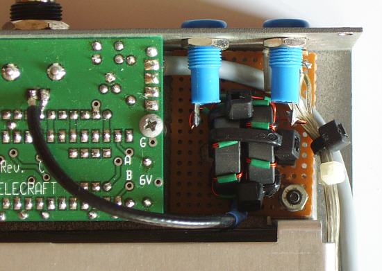
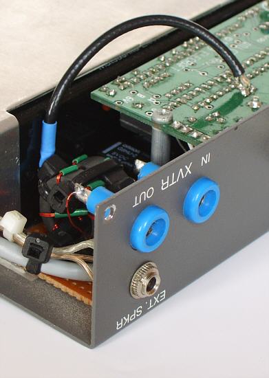
 I wound myself a copy of the balun, which I installed in the K2.
For the balun connections I use the holes on the back, which are reserved for the transverter.
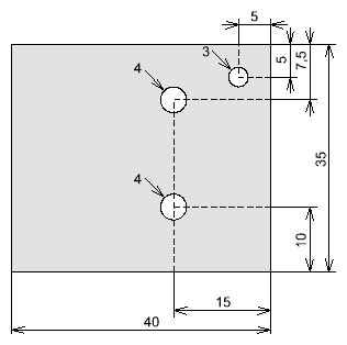
A small plastic slice or a piece of PCB serves as base for the attachement of the balun.
Secure the both cores with a third cable fixer on the base.
Screw tight the base at the bolt for the internal battery.
The connection from the 50 Ω side of the balun to the ATU must be a short coaxial cable.
This cable should be soldered as closely as possible to the balun.
Solder the other end of the coaxial cable on the underside of the internal ATU direct at the pads of the BNC jack.
[1] Ingo Meyer, DK3RED: Aufbau eines 4:1-Strombaluns für QRP. QRP-Report 4/2002, S. 9-14
RS232 interface
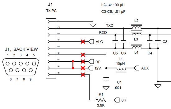 For the K2, there is an option called KIO2, which extends the transceiver with an RS232 interface.
Since this interface is also intended for the control of an external power amplifier, there are a few additional signals on the 9-pin D-sub jack.
If you connect a normal RS232 cable directly to the jack, some components on the KIO2 board will be destroyed.
Therefore, a special cable is described in the assembly and operation instruction.
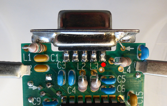
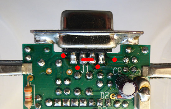 However, since I do not intend to connect a power amplifier, I modified the KIO2 board.
The traces on the connections 6 to 9 and 4 shall be interrupted in the places marked in the pictures.
Finally, the connections 7 and 8 are to be connected by a short wire.
Then a normal RS232 cable can be connected to control from a PC.
However, it is also possible to connect a suitable USB to RS232 adapter there.