 I needed a charger for a LiFePo4 batteries whose output voltage is exactly 14.4 V and whose has a current limit. I used a switching power supply here again, as I had already used it years ago with the charger for lead gel batteries. The output voltage and the current limit are relatively easy to adjust. There are only two resistances to be changed.
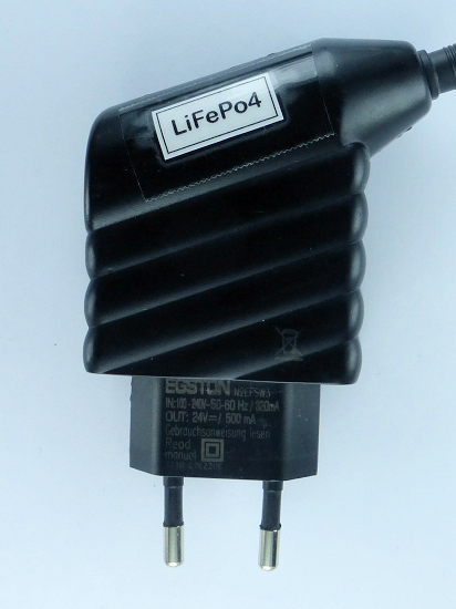
The manufacturer Egston provided the following data:
- N2EFSW3-12W
- Input voltage: 90 to 264 V
- Models: 9 V/1,3 A, 12 V/1,0 A, 15 V/0,8 A, 24 V/0,5 A
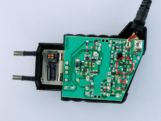
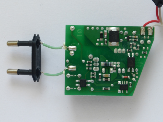
In the meantime, the part of the printed circuit board that points to the 230 V connector has been changed. But the half of the board on which the modification has to be made has remained the same.
 An important note! The circuit of the new printed circuit boards on the right is different. These power supplies can no longer be used for the conversion. In any case, I have not found a way. If a battery is connected to the output, they do not charge the battery. (Effective: 20.5.2020)
 Using the following formulas, it is possible to set any voltage UO (between 9 and 24 V) and any maximum current IO (up to 1.3 A). However, you should always consider the maximum output power of 12 W.
RU = 1,8889 · UO - 6,3333 with RU in kΩ and UO in V
RI = 4,7667 · IO + 0,1067 with RI in kΩ and IO in A
If you want to use this power supply for a different voltage, you will find a suitable calculation aid here.
 The housing is glued to the sides.
Lift both halves of the housing at the cable entry starting with a flat narrow object apart.
It's hard work, but it's possible.
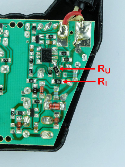
Change the marked resistors on the board according to your wishes.
If parallel-connected resistors are required, simply solder them on top of each other (like a sandwich).
Glue the housing back.
Finished!
For my conversion I used a power supply for 15 V/0.8 A.
For RU, I used 3 resistors (56 kΩ, 56 kΩ, 82 kΩ) in parallel and thus achieved an output voltage of 13.8 V.
Although I tried the current limit with different resistors.
In the end, however, I reinstated the original resistors with 3.92 kΩ for 0.8 A, as it was sufficient for my purpose.