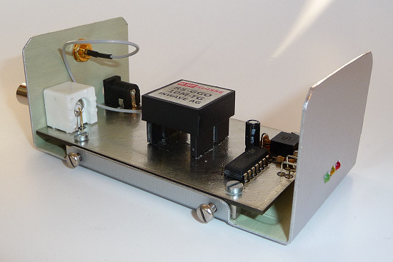
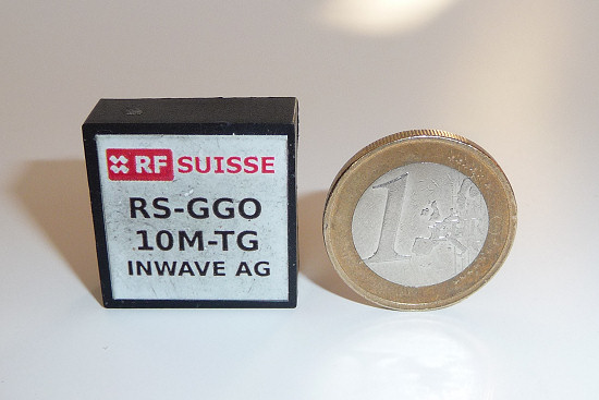
 Base of the 10 MHz frequency standard is a compact modul with the appellation RS-GGO10M-TG.
This modul is produces by Inwave AG under the label RF Suisse.
It is a GPS guided Oscillator (GGO), which works with a GPS receiver as Temperature Compensated Crystal Oscillator (TCXO).
Minimal only the power supply of 5 V and an active GPS antenna are to connect.
Within a few minutes a high-stable signal with 10 MHz is available.
 Specifications of the RS-GGO10M-TG
- Output frequency: 10 MHz
- Stability: free running < 2.5 · 10-6 (±25 Hz)
locked < 1 · 10-8 (±0,1 Hz)
typical < 5 · 10-9 (±0,05 Hz)
- Output: 3.3 V CMOS
- Active antenna: 50 Ω, 3.3 V, < 35 mA, Connector U.FL
- Power supply: 5 V, < 65 mA,
typical 45 mA (without current for active antenna)
- Dimensions: 2,5 × 2,5 × 1 cm
- Weight: 7 g
- Source of supply: was Box 73 and RF Suisse (www.rf-suisse.ch), Datasheet
Circuit diagram
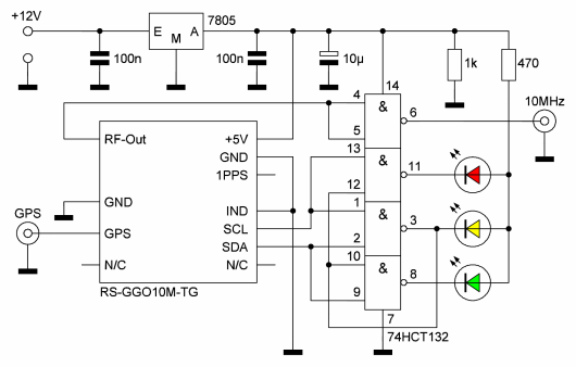 In order to recognize the status of the module, LEDs can be attached.
In the simplest case a duo-color LED is enough.
The different colors mark the status.
- red: no GPS signal available
- yellow: regulation actively
- green: 10 MHz signal OK
Since duo-color LED's do not assure to me optically, I use 3 separate LED's.
The logical combination takes over 3 NAND-gates of the 74HCT132 (Schmitt trigger).
Gate number 4 serves as buffer for the 10 MHz output.
I use a regulator for 5 V to operate the frequency standard also with 12 V.
Printed circuit board
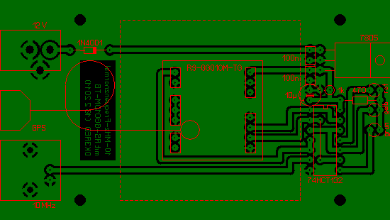 The printed circuit board is 5,6 × 9,9 cm largely and double-sided.
It fits into an aluminum housing, which I buy at Reichelt Elektronik (order no. TEKO BC1).
I have reduced the height of the housing to the here necessary measure.
The top side of the board serves mainly as heat sink for the voltage regulator.
Therefore also a one-sided board is usable.
Only under the 74HCT132 is located a bridge.
All conductor paths are arranged on the buttom side.
Who does not want to develop the circuit on a universal board, who can also use my finished layout.
For the design I used the program Sprint-Layout by Abacom, for which a free viewer is available.
Antenna
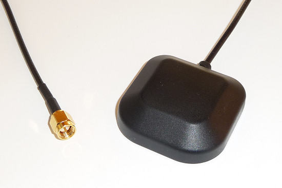 As GPS antenna any active antenna is usable, which is designed for 50 Ω, works with 3,3 V and does not required a current greater than 35 mA.
I use the antenna ATN-555 available at Sander Electronic.
(Note: The antenna is not listed in the online shop. Send your request by email.)
The ANT-555 possesses a SMA connection with a 5 m coaxial cable and a magnetic foot.
Since the module RS-GGO10M-TG possesses only a very small U.FL plug, I recommend the 10 cm long adapter cable of SMA on U.FL.
Thermically isolation
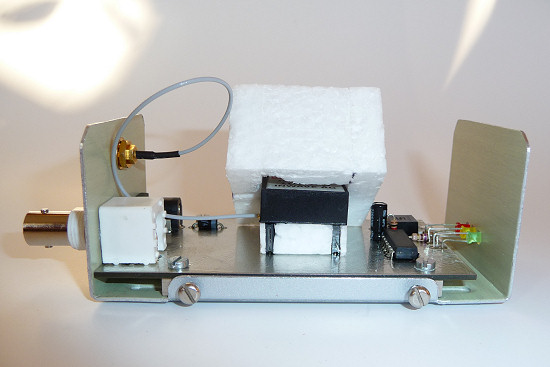 In order to be able to use a 10 MHz signal as stable as possible, two things are to be considered.
On the one hand the GPS antenna should be attached with a maximum possible free view to the sky.
On the other hand the module should operate in a thermally isolation.
To the fulfillment in the simplest case a thick isolation made with polystyrene sheets is sufficient.
I use 10 mm thick sheets, which I cut to shape properly and join with glue.
I inverted this cap over the module, under which likewise a sheet are located as isolation.
The module is mounted on 10 mm high sockets strips.